DETERMINATION OF SURFACE CARBON
PRINCIPLES OF OPERATION AND TYPICAL USE
The amount of the surface carbon on steel has been shown to have a direct affect on how well the steel will accept various types of coatings. Also, the measurement of the surface carbon on several types of materials is used to determine cleanliness. This procedure is used to measure the amount of surface carbon on a variety of materials. The instrument and method described allows for the differentiation of organic and inorganic surface carbon. This method has been performed successfully on coupons of cold-rolled steel, zinc plated steel, stainless steel, aluminum, titanium, and surface mount components.
The system is composed of a “Two Zone Combustion Furnace” and a “CO2 Analyzer” or, optionally, a programmable Infrared Furnace capable of very high temperature ramp rates. The sample is first placed in the cool zone of the combustion tube. Then, the system is given time to purge itself of any atmospheric CO2 that may have entered when inserting the sample. After purging, the sample is moved into the first zone of the furnace with a manipulator rod or hook ladle. This zone is set at a temperature of 460°C and all organic surface carbon on the sample is oxidized to CO2. The gases then go through the second zone heated to 590°C where any incomplete combustion products are “burned” and converted to CO2. After this, potentially interfering gases are removed by a series of post-scrubbers. The carrier gas is then introduced into the CO2 Analyzer where the carbon dioxide is detected, measured quantitatively, and displayed as µg of carbon.
Once all the organic carbon is liberated the sample can then be analyzed for inorganic surface carbon if desired. This is achieved by moving the sample into the second heat zone. Here, the inorganic surface carbon is oxidized to CO2. The gases then go through the same series of post-scrubbers as before. Again, the CO2, is detected and measured quantitatively by the CO2 Analyzer.
APPARATUS
- CM190 Surface Carbon Analyzer
Includes: CM5018 CO2 Coulometer Furnace
-or-
CM180/R Surface Carbon Analyzer
Includes: CM5018 CO2 Coulometer
CM5600 Programmable IR Furnace
Optional Catalyst Furnace
- Oxygen regulator capable of regulating to 7-10 psi.
- Coulometrics Interface Software (optional)
PROCEDURE
ASSEMBLY
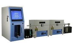
Assemble the CO2 Analyzer and Dual Zone Furnace as instructed in each of their respective manuals. (See Figure 1 for an example of the finished set up)
Notes:
The system is designed to accommodate either 15 mm or 25 mm combustion tubes. The 15 mm tube allows for coupons of 0.4 inch width and less to be introduced into the furnace. Generally, the coupons, used are 4 inches long but coupons up to 8 inches long have been used successfully. The 25 mm tube allows for coupons of up to 0.75 inches wide to be introduced into the furnace. The same length limitations of the smaller width coupon holds true for the larger coupons.
Most samples are introduced using either a manipulator rod or hook ladle. Typically, a 1/8 inch hole is made at one end of the coupon and the rod or ladle is hooked through this hole. Hook ladle introduction only allows for the measurement or organic surface carbon.
There are a variety of sample introduction methods for analyzing surface carbon. For technical assistance contact the UIC Applications Laboratory.
ANALYSIS
Sample Preparation and Handling
Metal coupons are usually cut into appropriate sizes with either a die (ideally) or with shears. If a die is used, a hole is punched in the end of the strip at the same time the piece is punched. If shears are used, a hole is drilled at one end of the strip after the piece is cut.
No matter what type of samples are being analyzed it is recommended that they be stored in plain manila style envelopes prior to analysis. If possible, the samples can be stored in a clean, closed glass container such as a dessicator. Plastic bags are not recommended for storage as they can cause contamination and high results.
Samples should be handled with clean tweezers at all times to avoid contamination. Also, it is recommended that samples be analyzed as soon as possible after cutting or cleaning. Every time the samples are exposed to the air they can become contaminated with amounts of carbon measurable by this technique.
Blank Determination
Once the system is assembled and the combustion tube conditioned, sample analyses can begin. Set up the CO2 Analyzer’s coulometric cell as instructed in the manual. Connect the Furnace to the CO2 Analyzer. The flow rate is usually set to 100 ml / minute. (Up to 200 ml / minute has been used successfully.) Insert the manipulator rod into the breech block or the ladle into the “cool zone” of the combustion tube and seal the system. Allow the system to purge itself of any atmospheric carbon dioxide that may have entered when the sytem was opened. The purge time will depend on the size of combustion tube being used and the carrier gas flow rate. It is usually 1 to 5 minutes. Determine the background rate of the system by entering “blank” as the sample name in the Sample Entry screen of theCM5018 CO2 Coulometer. Press “Enter” to begin the analysis and then insert the sample introduction device being used into the first heating zone. (At this point there are no samples in the furnace.) The CM5018 will automatically determine and store the blank value according to the user selectable settings saved within the system’s memory. (If inorganic surface carbon is going to be analyzed, slide the manipulator rod into the second heating zone half way through the blank determination.) The instrument will use the saved blank value in calculating the final result values.
Sample Analyses
At the end of the blank run remove the rod or ladle from the furnace. If a ladle is being used slide it into the cool zone of the furnace and leave it there for a few moments to cool. Then, remove it from the combustion tube and place it on a clean heat-resistant surface. A glass plate or beaker is often used. If a manipulator rod is being used, unscrew the end of the breech block holding the rod and pull the rod out of the combustion tube without sliding it through the Teflon ferrules that seal around it. Sit this assembly on the lab bench to cool in such a way that it will not become contaminated. Often, it is hung from the edge of the lab bench by the breech block plug using a ring stand and clamp.
One cool, place a sample on the sampling device and insert the sample into the cool zone of the combustion tube. Seal the system and allow for the purge time. Start the CO2 Analyzer and insert the sample into the first zone of the furnace. The analysis endpoint will be automatically determined by the CM5018 according to the user selectable settings saved within the instrument. Individual coulometer readings and final results are printed to an attached printer. A summary report of up to 50 samples will be printed and, if desired, saved to diskette at the end of the analysis session.
If the determination of inorganic surface carbon is desired, start the CO2 Analyzer again and move the sample into the second zone of the furnace. Again, the CM5018 will automatically determine the endpoint and print the results. Optionally, when using the CM5600 Programmable IR Furnace, the CM5018 can be run in “autosampler” mode which will automatically prompt the IR furnace unit to ramp to the next temperature level to cool to the beginning value when the analysis is finished.
Note: It is important that each time a sample is analyzed it is placed into each heating zone at the same place. This helps insure consistent combustion temperatures.
Calibration
Although calibration is not required, the instrument’s performance can be checked using a sucrose standard. (Benzoic acid and dioctyl sebacate have also been used.) If solid sucrose is to be used, first determine the background rate of the system using a scoop ladle and a small platinum boat. After determining the background rate with this type of sample introduction, weigh an appropriate amount of sucrose into the platinum boat and analyze.
A more ideal instrument performance check would be to take a sample that has been “burned in” and spike the sample with a known quantity of sucrose solution. (“Burned in” means that the sample was previously analyzed and then kept clean.) Then analyze this sample and calculate recovery. The user should establish acceptance criteria for whichever type of performance check is used.
RESULTS
The sensitivity of the CO2 Analyzer is better than 1 µg C. Overall accuracy is limited by the reproducibility of successive background measurements. Using standard materials, deviations are typically better than 0.15% relative or ± 1 to 2 µg of C (whichever is greater). Sample homogeneity normally limits the accuracy of the analysis rather than the instrument’s capability.
Note: This technique is appropriate only for sample materials which do not contain compositional carbon that will react at the analysis temperature.
REFERENCES
Basu, R.S., P.B. Logsdon, and E.M. Kenny-McDermott. “Precision Cleaning in Aerospace Industry with HCFC Based Blend.” Proceedings of the International Conference on CFC and Halon Alternatives. 1991. 188-198.
Basu, R.S., K.P. Murphy, and E.M. Kenny-McDermott. “Hyroflourocarbon Solvents in Precision Cleaning.” Proceedings of the National Electronic Packaging and Production Conference – West ’94. March 1-3, 1994. 237-247.
Bonner , Dr. J.K. and J.M. Lewis “Coulometry: a Promising Method for Quantifying Organic Residue on SMC’s (Surface Mount Components) After Cleaning.” Buffalo, NY: Allied-Signal Corporation, Buffalo Research Laboratory.
Coduti, Dr. Phillip L. “Effect of Residual Carbon on the Paintability of Steel Strips.” Technical paper presented at the Association for Finished Products of SME. October 1978. Paper No. FC78-575.
Coduti, Dr. Phillip L. and Dr. Don E. Smith. “How Clean is Clean – A Technical Evaluation of Cleanliness.” Technical paper presented at the National Coil Coaters Association Fall Technical Meeting. Sept.30 – Oct.2, 1979.
Coduti, Phillip L. and Donald G. Earl. “Cleanliness Measurement Techniques on Sheet Steel Surfaces.” Technical paper presented at the 41st Porcelain Enamel Institute Technical Forum, Oct. 8 – 10, 1979: 167-
Coduti, Phillip L. “A Quantitative Method for the Determination of Sheet Steel Surface Cleanliness.” Technical paper presented at the American Electroplaters Society’s Fourth Continuous Strip Plating Symposium. May 3, 1984.
Coduti, Phillip L. “Effects of Steel Processing on the surface Carbon of Cold-Rolled Steel.” Technical paper presented at the American Society for Metals / American Deep Drawing Research Group Conference: Technological Impact of Surfaces: Relationship to forming, welding, and painting. April 14, 1981.
Coduti, Phillip L. ”Relationship of Surface Cleanliness and Surface Chemistry to the Corrosion Performance of Painted HSLA Steels for Exposed Automotive Applications.” Automotive Corrosion by Deicing Salts. Ed. Robert Baboian. Houston, TX: National Association of Corrosion Engineers, 1981. 363 – 376. (Also presented as a technical paper at the National Association of Corrosion Engineers “International Corrosion Forum”. March 3-7, 1980. Paper No.140)
Coduti, Phillip L., Richard Hoch, and P. Lawrence Meschi. “Carbon Coulometry: Direct Cleanliness Verification for Alternative Cleaning Technologies.” Precision Cleaning Vol. III, No.1 (January 1995): 53-61.
Coduti, Phillip L., James E. deVries, and Larry P. Haack. “Measurement of Carbon on Cold-Rolled Steel: A Comparative Study Using Surface Analytical and Coulometric Methodologies.” Industrial Engineering Chemical Research 33 (1994): 2618-2630.
King, Arthur E. “Direct Determination of Carbon on Metal Surfaces.” AFP/SME Technical Paper FC78-584. Dearborn, MI: Association for Finishing Processes / Society of Manufacturing Engineers. 1978.
King, Arthur E. “Review of Combustion — Coulometric CO2 Detection Method for Direct Determination of Carbon on Metal Surfaces.” Technical paper presented at AFP/SME – Surface Conditioning and Coating: Today and Tomorrow. March 1981.
Pumea, R.W. and J.M. Stadnik, Jr. “Characterising Steel Surface Cleanliness Utilizing Statistical Methods for Data Analysis.” Technical paper presented at the Second International Symposium on Statistical Process Control and Sensors in the Steel Industry. Aug. 28-31, 1988.