DETERMINATION OF CARBON DIOXIDE IN AMINE GAS SCRUBBING SOLUTIONS

PRINCIPLES OF OPERATION AND TYPICAL USE
This procedure is typically utilized for the analysis of amine solutions which are used to remove environmentally-controlled emissions from flue gases. This method measures the amount of carbon dioxide (CO2) in the scrubbing solution. This result is used along with other analyses to determine the amine scrubbing solution’s efficiency and remaining capacity.
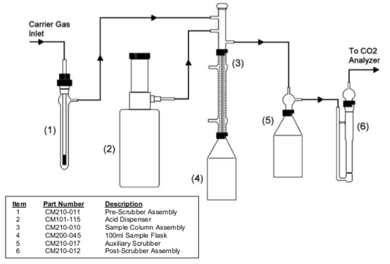
The system is composed of an “Acidification Module” and a “CO2 Analyzer”.TheAcidification Module is purged of atmospheric CO2 with an inert carrier gas. After purging the system, an aliquot of the amine solution is injected into the sample flask. Acid is then added using the dispenser on the Acidification Module. The gases evolved from the acidification of the sample then pass through a solution containing silver nitrate, where potentially interfering gases are removed from the carrier gas stream. Finally, the carrier gas is introduced into the CO2 Analyzer where the carbon dioxide is detected and measured quantitatively.
APPARATUS
- CM140 Total Inorganic Carbon Analyzer
Includes: CM5018 CO2 Analyzer or equivalent
CM5330 Acidification Module or equivalent
- CM210-017 Auxiliary Scrubber Assembly with 100ml Flask, Threaded
- Ring stand with standard type clamp for holding glassware
REAGENTS
- Pre-Scrubbing Solution: 40 to 45% Potassium Hydroxide Solution (KOH) (Note: The pre-scrubbing solution is needed only if the “internal” carrier gas of the Acidification Module or a low purity external carrier gas is being used.)
- Acid: 2 to 4N Sulfuric Acid (H2SO4)
- Post-Scrubbing Solution: 20% Silver Nitrate (AgNO3) (Note: This solution can be made using reagent water containing 3% Hydrogen Peroxide (H2O2) and acidified with Nitric Acid (HNO3)to pH 2.)
- CM300-001 Carbon Cathode Solution
- CM300-002 Carbon Anode Solution
- CM300-003 Potassium Iodide (KI)
- External Carrier Gas (optional) (Note: An external carrier gas, such as nitrogen, helium, or CO2 free air may be used in place of the “internal” air source of the Acidification Module if desired.)
PROCEDURE
ASSEMBLY
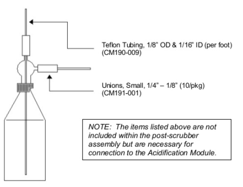
Assemble the Acidification Module and the CO2 Analyzer as instructed intheir respective manuals. Place the auxiliary scrubber in-line between the sample column assembly and the post-scrubber assembly of the Acidification Module. Hold the auxiliary scrubber in place using a ring stand and clamp. (The auxiliary scrubber consists of two parts. The bottom is a 100 ml sample flask like the ones used on the Acidification Module. The top is an adapter that allow the gas that is bubbled through the solution to exit. See FIGURE 1 for the assembly of this scrubber.)
The post-scrubber assembly is snapped into place on the right front of the Acidification Module. This fritted scrubber is used as an indicator of when the auxiliary scrubber is spent. When the silver nitrate solution reacts with hydrogen sulphide (H2S) generated from the sample acidification, a black precipitate forms.When this precipitate begins to form in the post-scrubber assembly at a substantial rate, the silver nitrate solution in the auxiliary scrubber should be replaced.
Place a stir bar in a 100 ml sample flask and attach the flask to the bottom of the condenser on the Acidification Module. Secure the flask with the red locking ring. Place the flask and assembly into the heating and stirring port of the Acidification Module. Heating is not normally required so the condenser does not need to be connected to a cooling source. If an external carrier gas is used, adjust the pressure of the system 2-5 psi. Set the flow to 100 ml/min. Using the flow meter on the front of the Acidification Module. (See Figure 2 for an example of the set-up and flow diagram.)
ANALYSIS
Determine the background rate of the system by entering “blank” as the sample name in the Sample Entry screen of theCM5018 CO2 Coulometer. Press “Enter”to begin the analysis. The CM5018 will automatically determine and stroke the value according to the user selectable settings save within the system’s memory. The instrument will use the saved blank value in calculating the final result values.
To perform an analysis, draw the sample into a syringe that is fitted with an injection needle. (See note on “sample integrity”.) Usually 250 to 500 µl of sample is used depending on the sample’s CO2 content. Start the CO2 Analyzer and inject the sample into the sample flask through the septum at the top of the sample column adapter. The analysis endpoint will be automatically determined by the CM5018 according to the user selectable settings saved within the instrument. Individual coulometer readings and final results are printed to an attached printer. A summary report of up to 50 samples will be printed and, if desired, saved to diskette at the end of the analysis session.
The weight of the sample can be determined in either of two ways. First, the syringe can be weighed before and after injection. The weight of the sample is determined by the difference between these two measurements. Second, if the density of the sample is known, the injection volume can be noted and the weight can be calculated. This method requires a volumetric syringe.
After a few samples are analysed, the blank should be re-established and occasionally checked throughout the day. The sample flask does not need to be emptied until it is almost full.
Although calibration is not required, the instrument’s performance can be checked using calcium carbonate (CaCO3). This is done by weighing 10 to 20 mg of CaCO3 into a small porcelain boat and placing it in a 10 ml sample flask. The sample flask is connected to the bottom of the condenser, purged, and then acidified. Alternatively, the user may use a liquid standard to verify the instrument’s performance. Io prepare a 1000 mg C/L solution, weigh 0.3500 g of sodium bicarbonate and 0.4428 g of sodium carbonate and transfer both to the same 100 ml volumetric flask. Bring to volume with reagent water. The user should establish acceptance criteria for whichever type of performance check is used.
NOTE: Sample Integrity … Because of the ability of amine solutions to absorb CO2, sample handling is extremely important. The collection should be collected into bottles with septum tops. The septum top allows the sample to be drawn into the injection syringe without opening the sample bottle.
RESULTS
The analysis is normally limited to the precision of the sample volume measurement. Typical overall accuracy is ±0.5% relative with a titration of ±0.15% relative.
Assuming that the system is clean and that high purity water and acid are used, blank rates as low as 1 to 2 µg of carbon in 10 minutes are typical. Normally, blanks lower than µg of carbon per minute are accepted.
REFERENCES
This method is similar to:
ASTM D 513. “Standard Test Method for Carbon Dioxide in Water; Method G, Coulometric Titration Method.” Annual Book of ASTM Standards. Philadelphia, PA: American Society for Testing and Materials.