Simultaneous Determination Of Carbon Dioxide And Hydrogen Sulfide In Amine Gas Scrubbing Solutions
PRINCIPLES OF OPERATION AND TYPICAL USE
This procedure is typically utilized for the analysis of amine solutions which are used to remove environmentally-controlled emissions from flue gases. This method measures the amount of carbon dioxide (CO2) and the amount of hydrogen sulphide (H2S) in the scrubbing solution. This result is used along with other analyses to determine the amine scrubbing solution’s efficiency and remaining capacity.
The system is composed of an “Acidification Module”, “CO2 Analyzer” and an “SO2 Analyzer”. The Acidification Module is purged of atmospheric CO2, SO2 and H2S with an inert carrier gas. After purging the system, an aliquot of the amine solution is injected into the sample flask. Acid is then added using the dispenser on the Acidification Module. The gases evolved from the acidification of the sample then pass into the special cell of the SO2 coulometer where SO2 and H2S are absorbed into the solution and titrated.
CO2 is not absorbed into the sulphur detector solution and provides no interference. The CO2 enriched carrier gas is then routed to the CO2 analyzer where it is absorbed and automatically titrated.
APPARATUS
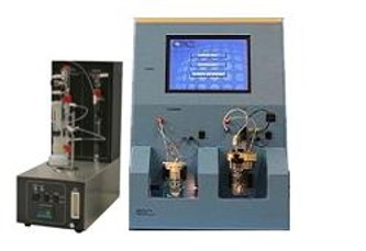
Simultaneous Carbon/Sulfur Analyzer
Includes: CM5017 CO2 Analyzer
CM5017S SO2 Analyzer
CM5330 Acidification Module
Special, air-tight sulphur cell
REAGENTS
- Pre-Scrubber Solution: 40 to 45% (wt/vol) potassium hydroxide (KOH)
- Post Scrubber Solution: 3% (wt/vol) silver nitrate (AgNO3), acidified to pH 3
- Acid: 2 to 4N Sulfuric Acid (H2SO4)
- CM300-001 Carbon Cathode Solution
- CM300-002 Carbon Anode Solution
- CM300-003 Potassium Iodide (KI)
- CM300-026 Sulfur Anode Solution
- CM300-027 Sulfur Cathode Solution
- External Carrier Gas (optional) (Note: An external carrier gas, such as nitrogen, helium, or CO2- free air may be used in place of the “internal” air source of the Acidification Module if desired.)
PROCEDURE
ASSEMBLY
Assemble the Acidification Module,SO2 Analyzer and the CO2 Analyzer as instructed in their respective manuals. It is especially important to ensure that the special sulphur analyser cell is leak free and that the flow from the acidification module always passes through the SO2 analyzer first. The cell solution in the CO2 analyzer is adversely affected by sulfur compounds and passing the carrier gas through the sulfur analyser first effectively removes all interfering compounds.
An optional solid silver or silver nitrate scrubber may be used in line between the sulfur coulometer and the carbon coulometer as an indicator of sulfur cell efficiency. Black precipitate in the silver nitrate solution or “graying” of the solid silver indicates that SO2 or H2S is not being properly absorbed into the sulfur cell solution.
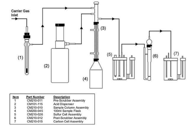
Place a stir bar in a 100 ml sample flask and attach the flask to the bottom of the condenser on the Acidification Module. Secure the flask with the red locking ring. Place the flask and assembly into the heating and stirring port of the Acidification Module. Heating is not normally required so the condenser does not need to be connected to a cooling source. If an external carrier gas is used, adjust the pressure of the system to 2-5 psi. Set the flow to 100 ml/min. using the flow meter on the front of the Acidification Module. (See FIGURE 2 for an example of the set-up and flow diagram.)
ANALYSIS
Determine the background rate of the system by entering “blank” as the sample name in the Sample Entry screen of both CM5017 CO2 Coulometer and the CM5017S SO2 Coulometer. Press “Enter” on both units to begin the analysis. The coulometer will automatically determine and store the blank value according to the user selectable settings save within the system’s memory. The instrument will use the saved blank value in calculating the final result values.
To perform an analysis, draw the sample into a syringe that is fitted with an injection needle. (See note on “sample integrity”.) Usually 200 to 300 µl of sample is used depending on the sample’s H2S content*. Start the coulometers and inject the sample into the sample flask through the septum at the top of the sample column adapter. Add 5 to 10 ml of acid to flush the sample through the sample column line. The analysis endpoint will be automatically determined by the coulometers according to the user selectable settings saved within the instruments. Individual coulometer readings and final results are printed to an attached printer. A summary report of up to 50 samples will be printed and, if desired, saved to diskette at the end of the analysis session.
*Note: Due to lower H2S solubility in the sulfur cell solution sample sizes should be adjusted to allow no more than 2500ug S per sample at a 100ml/minute flow rate.
The weight of the sample can be determined in either of two ways. First, the syringe can be weighed before and after injection. The weight of the sample is determined by the difference between these two measurements. Second, if the density of the sample is known, the injection volume can be noted and the weight can be calculated. This method requires a volumetric syringe.
After a few samples are analysed, the blank should be re-established and occasionally checked throughout the day. The sample flask does not need to be emptied until it is almost full.
Although calibration is not required, the instrument’s performance can be checked using calcium carbonate (CaCO3) and Sodium Sulfite (Na2SO3). This is done by weighing 10 to 15 mg of CaCO3 and 5 to 10mg of Na2SO3 into a small porcelain boat and placing it in a 10 ml sample flask. The sample flask is connected to the bottom of the condenser, purged, and then acidified. Alternatively, the user may use a liquid standard to verify the instrument’s performance. To prepare a 10,000 mg C-S/L solution, weigh 3.237 g of sodium bicarbonate, 4.428 g of sodium carbonate and 3.931 g of sodium sulphite and transfer all to the same 100 ml volumetric flask. Bring to volume with reagent water. This solution should yield 2000ug C and 2000ug S when using a 200ul injection. The user should establish acceptance criteria for whichever type of performance check is used.
NOTE: Sample Integrity … Because of the ability of amine solutions to absorb CO2, sample handling is extremely important. The collection should be done so that the sample has as little contact with the air as possible. Ideally, the samples should be collected into bottles with septum tops. The septum top allows the sample to be drawn into the injection syringe without opening the sample bottle.
RESULTS
Actual Results Using This System
| Sample | Wt. Range | # of Runs | Theory % H2S | Found % H2S | Std. Dev. | RSD | Theory % CO2 | Found % CO2 | Std. Dev. | RSD |
| CaCO3/ Na2SO3 | 5-15mg | 7 | 26.74 | 26.54 | 0.089 | 0.36% | 44.01 | 43.82 | 0.014 | 0.12% |
| Amine 1 | 200-400mg | 6 | —- | 0.35 | 0.003 | 0.73% | —- | 0.63 | 0.006 | 0.96% |
| Amine 2 | 200-400mg | 6 | —- | 1.21 | 0.004 | 0.34% | —- | 2.30 | 0.005 | 0.22% |
| Amine 3 | 200-400mg | 6 | —- | 0.24 | 0.005 | 2.23% | —- | 1.28 | 0.010 | 0.82% |
The analysis accuracy is normally limited to the precision of the sample volume measurement. The relative standard deviation for standard materials is better than 0.5%.
Assuming that the system is clean and that high purity water and acid are used, blank rates as low as 1 to 2 µg of carbon in 10 minutes are typical. Normally, blanks lower than 1 µg of carbon per minute are accepted.
FIGURE 2: Flow diagram of the Acidification Module including the SO2 and CO2 cell assemblies.